Apple Mac Mini M2 SL (Super Légère)


Partially inspired by the Snazzy labs M1 build (which made the smallest Mini possible) https://www.printables.com/model/139893-shrink-the-m1-mac-mini , another case mod for the M2 Mac Mini, this time focused on weight and power options. A failed attempt at creating a OSX based do-it-all mobile compute module.
While the Snazzy build went for a minimal size desktop, removing the original rear panel to reduce empty space, my build retained it for simplicity and as a result, still has empty space inside. Where the Snazzy build used a total of 6 separate 3D printed parts, I did it with one- a single housing sleeve with integrated antenna holder and mounting points. While the result is significantly larger than the Snazzy labs, the aim was light weight over small size.

Mini SL Ready to install with antenna already in Sleeve

Context
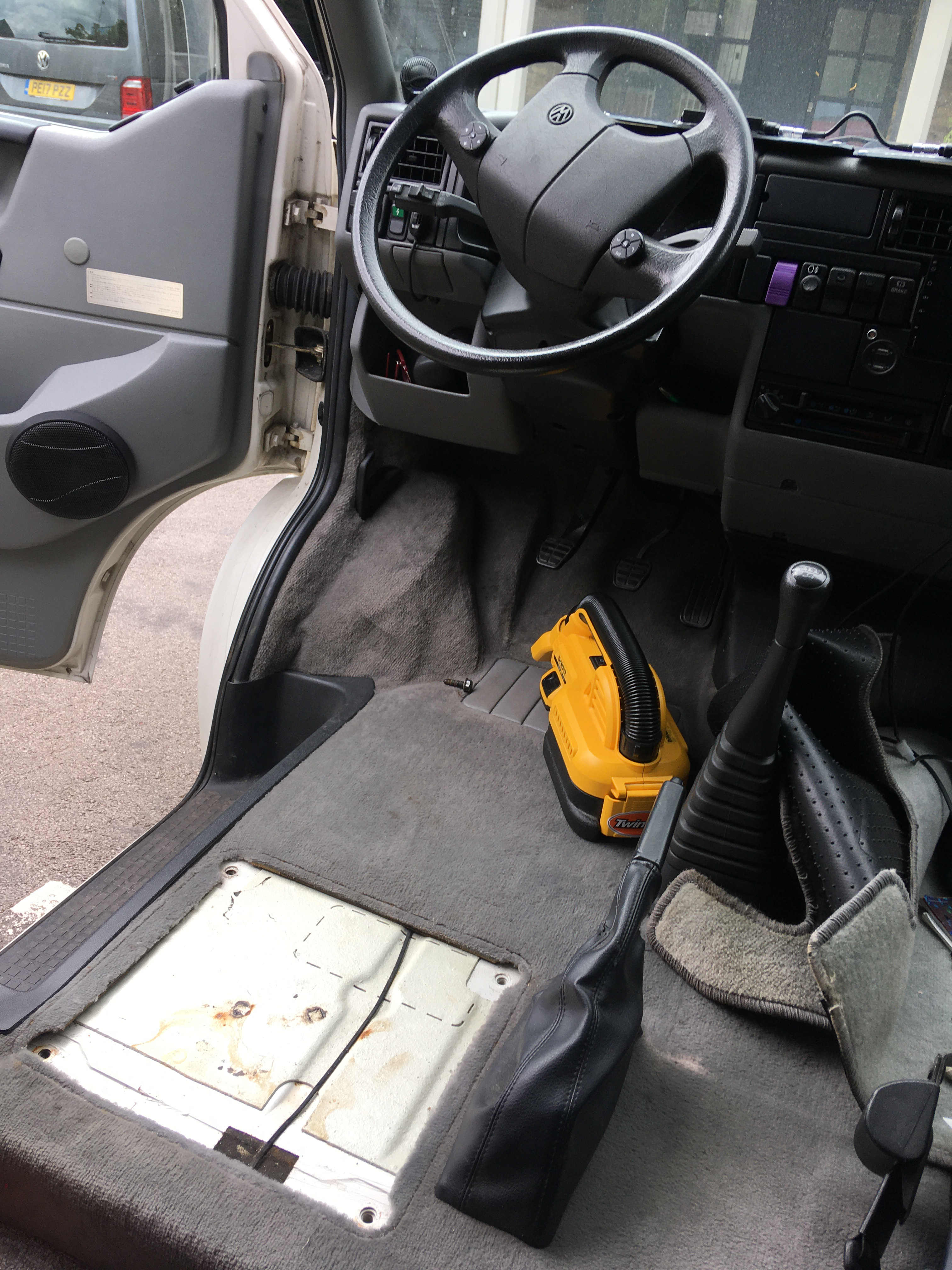
I have been using Macs since almost the beginning. I started using an iPad as my daily device for meetings and I started using stick PCs as a way of adding a full computer to my bag with minimal weight gain(replacing a laptop). Sometimes I need access to specialist PC software, sometimes its just desktop Outlook or Excel.
The stick PC was successful in the day, while it could be slow, when addressing a certain need, speed isn’t vital. The let downs were lack of storage, no internal network port and limited USB ports and power.

MiniSL alongside (its competition) the Mele PC

As I downsized my laptop to the excellent (but slow) Macbook 12″, I needed a better compute device to replace both the stick PC and a virtual PC. I moved to a NUC at this stage, selecting the new 7th gen i3 with its low TDP which allowed smaller PSUs. While the NUC added weight compared to a stick PC it gave me lots of power, storage, HDMI 2.0 (unusual at the time) and powerful USB ports (doubling as a USB Charger). It has served me well for 6 years, it found use not only directly connected to an iPad but also to drop places and remote into (I often need to be on two air-gapped networks).

Always looking for better solutions and the possibility of moving to OSX, I started considering replacing the NUC. Some of its failings are Duet display- while once reliable is completely unreliable now on PC. Getting connected to the NUC other than via remote desktop can be challenging. The NUC was also stuck on windows 10, while not really an issue, it highlights that its an aging machine.

Choosing a Mini
When the M2 came out, I did look at whether it would replace my quad core i7 2012 mini but the prices of apple storage is insane. In my view a desktop should have sufficient internal storage, its completely ridiculous that my 2012 Mini came with more storage than the 2023 Mini (it came with the base 500GB drive, most selected the 1TB Fusion drive option at that time). My 2012 mini now has 8TB of internal storage (in the form of 2 x 4TB Samsung SSDs). The limitations in what virtual machines the M2 can run is also a serious issue for for my main machine. I need to run not just Windows but other VMs for appliances and OS. So storage and processor ruled it out as a primary machine.

Some of the things I hate in the design of the M2 as a desktop make it a great mobile device- the lack of expansion makes for small components. It became easy to select the base mini for my intended use as a mobile unit. . The smallest processor reduces powering issues, the base storage limits cost (for something I am hacking)and its is the best value. I did consider an old M1 with its slightly lower power consumption, slightly lower cost but I didn’t think it was worth it for a much older machine.
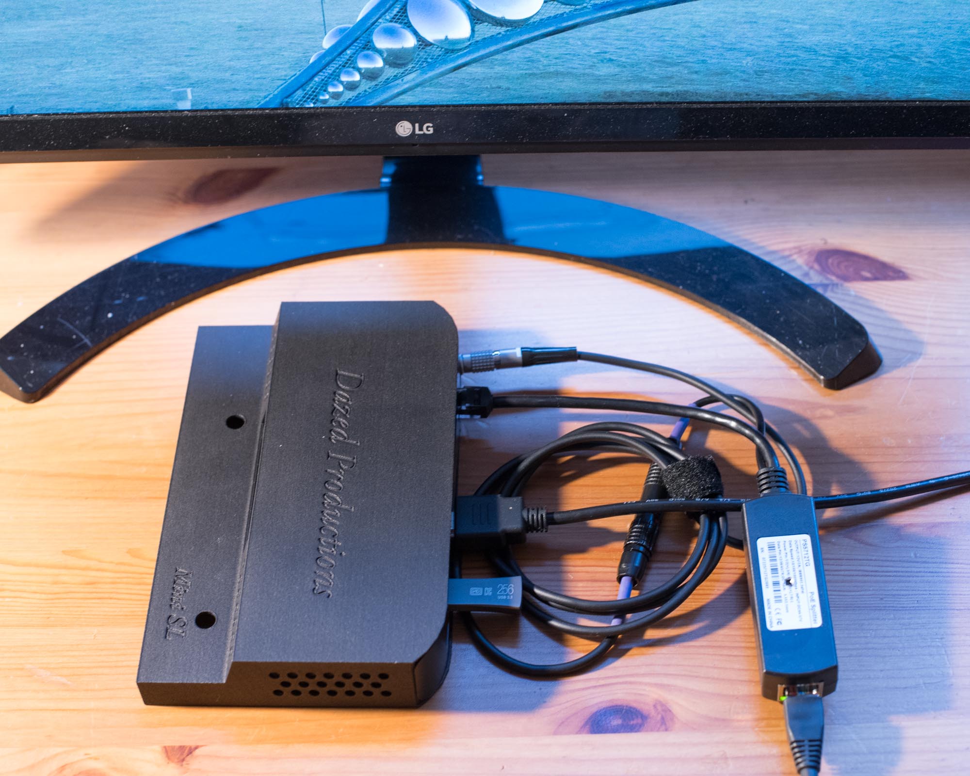
Build
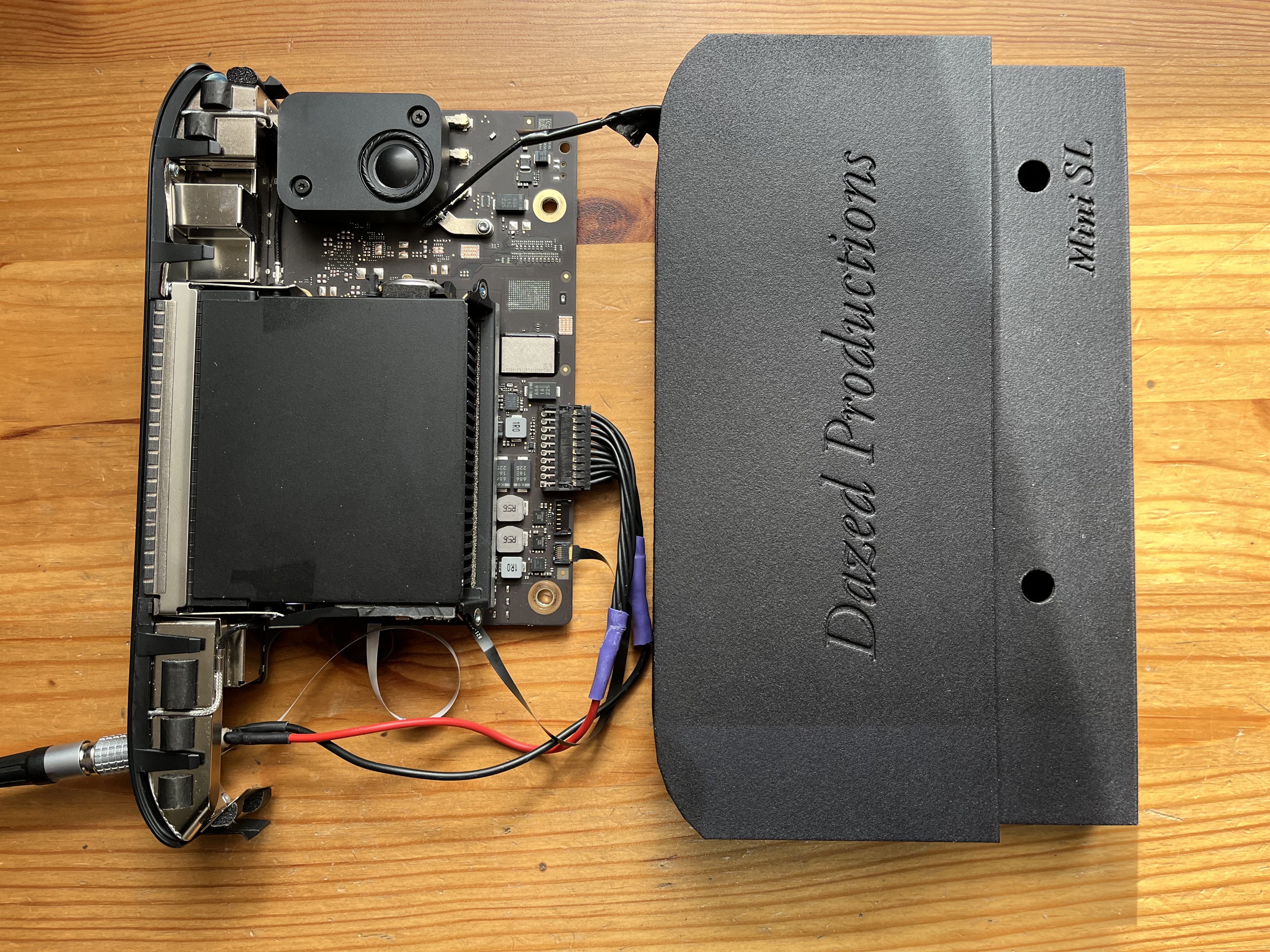
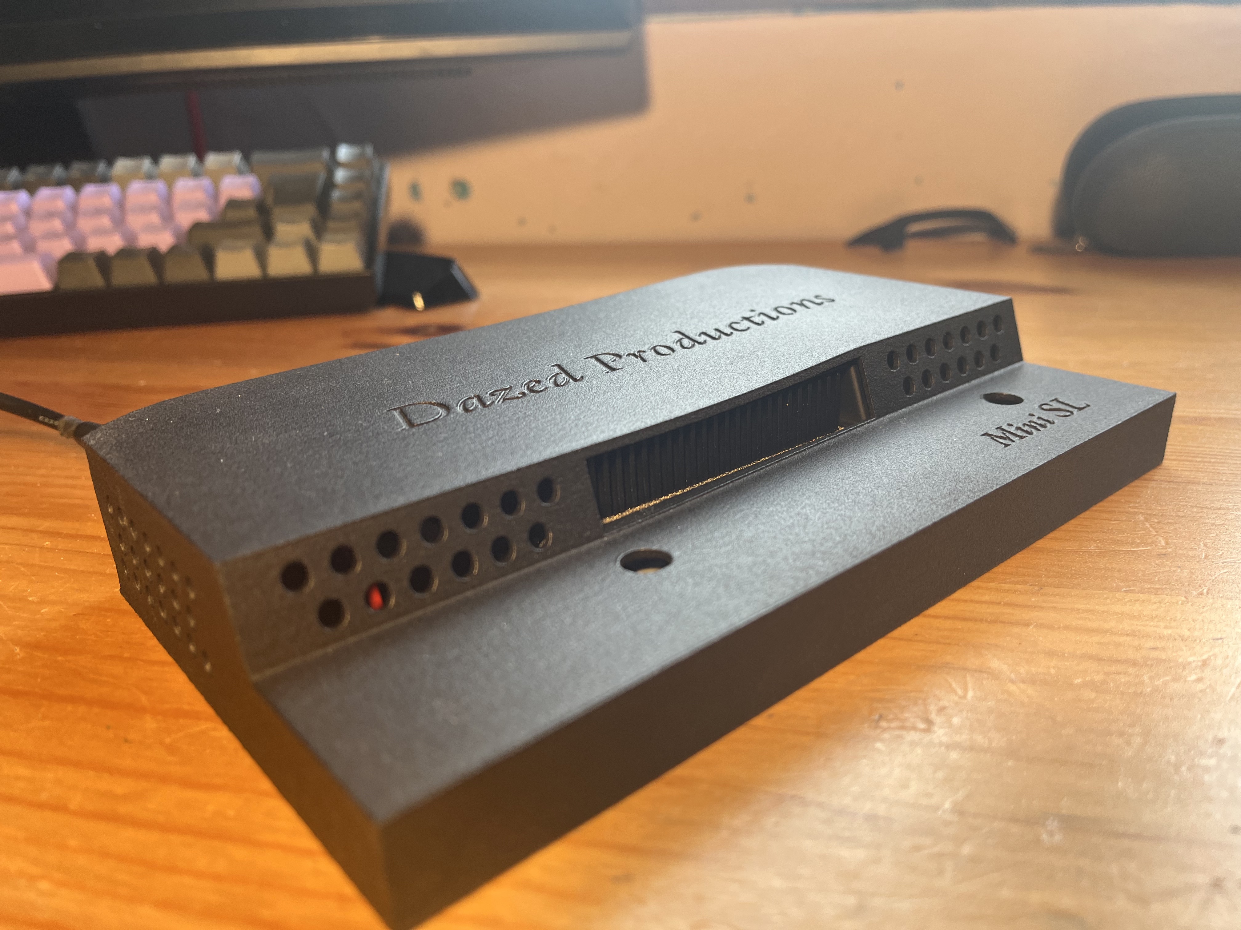
This is a first print from a 3D design, so not without flaws/observations! I am actually quite happy it didn’t need any modifications at all. It was designed in Autocad and printed using MJF technology with PA12 material at a commercial lab (Weerg). It features the same mounting points as the Apple chassis and the mounting points have guide holes for a M2.5 tap (so its held in place with the standard two PCB screws.
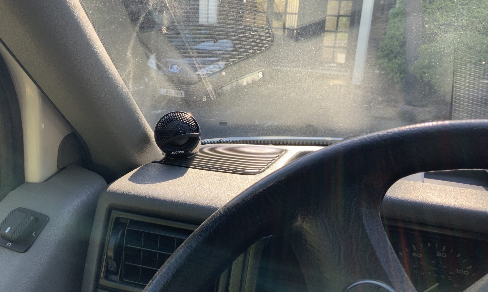
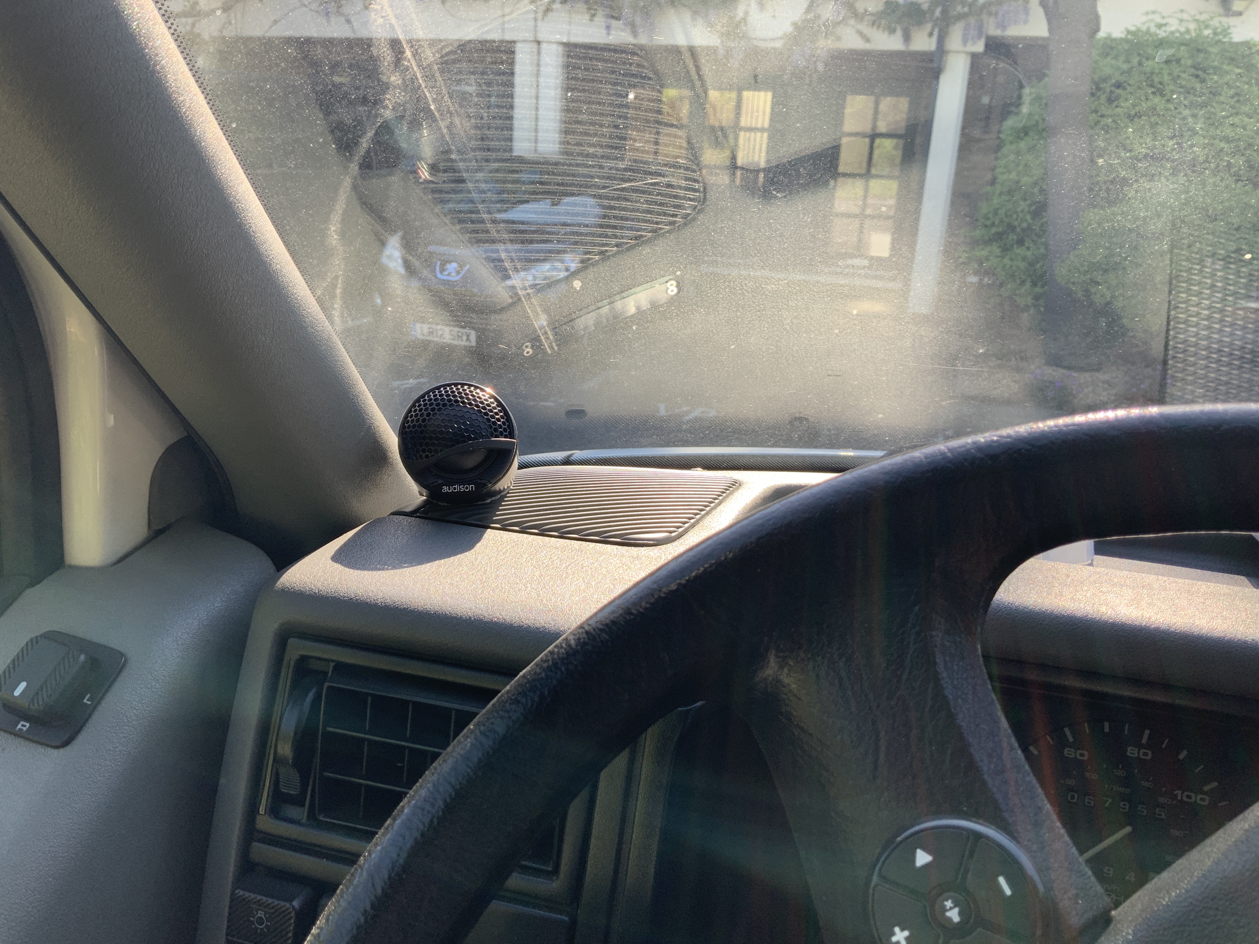
The housing includes a sleeve above the speaker for the antenna.
While my initial thoughts were to retain the fan, after running the Mini as a bare PCB for a few weeks and watching temperatures, I decided to delete the fan as it was running so cool.
I decided to keep the heatsink shroud and match the housing to it, the intent being that hot air would exit from the case rather than circulating inside.

MiniSL with its exposed heatsink

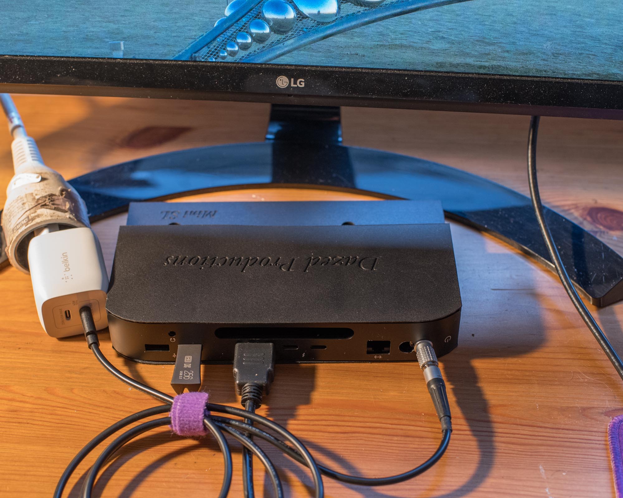
For powering the mini, I wanted a solution that gave easy access to power and didn’t add weight. There were 3 main powering solutions that I chose.

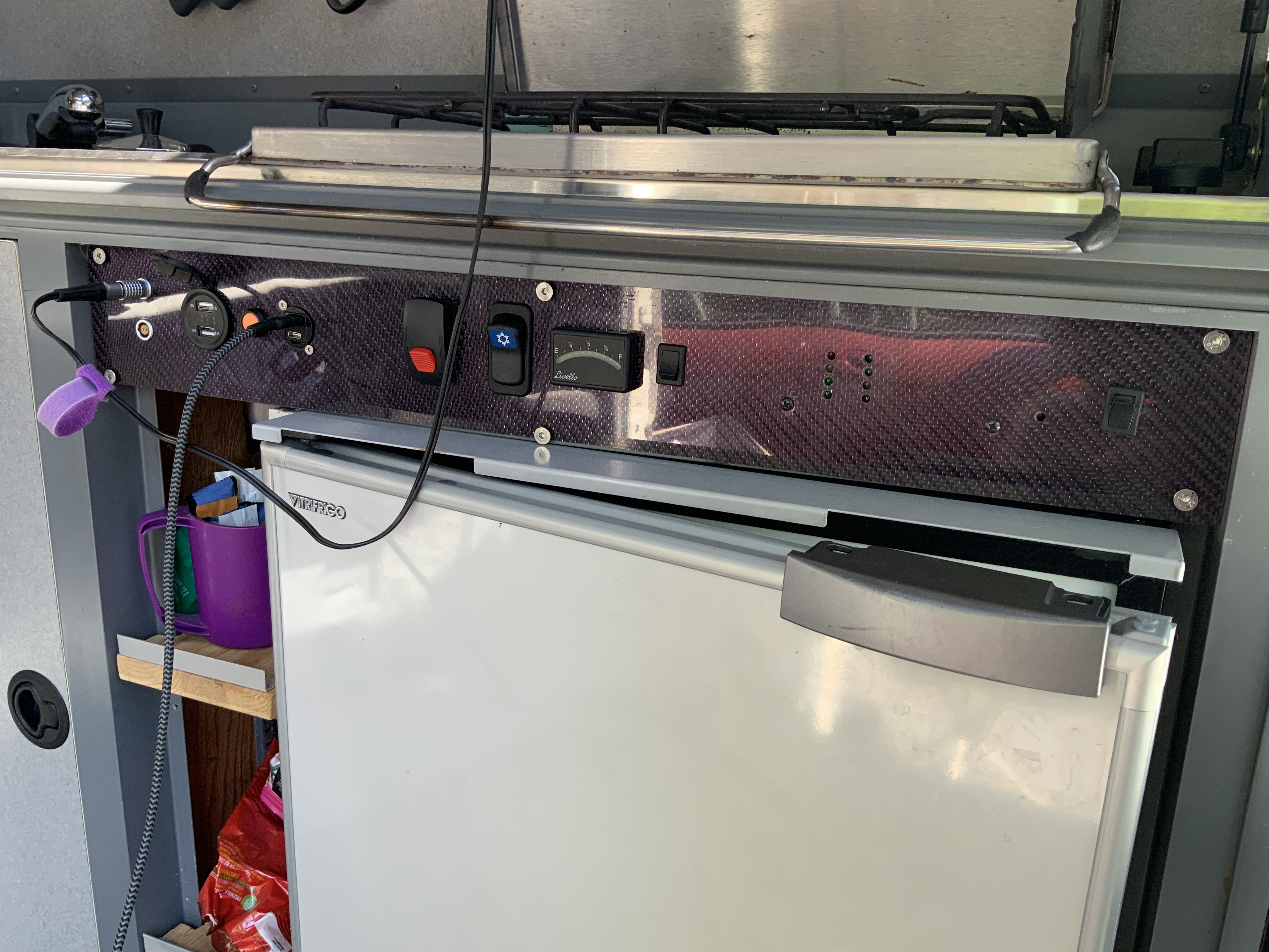
POE- where I work and at home I have easy access to PoE+. While 60W PoE++ exists, its not common on switches and PoE extractors tend to be physically larger, I therefore used a 12V 2A PoE extractor (30W).

USB-C PD- I have to carry a usb-C power supply as it is, and I generally carry an Anker PD-1, which is 30W and super light. I found USB Power cables that break out USB-C to either 12V or 15V. I used 15V as this is a more common PSU Specification.

Battery- To use in my van, and potentially mobile, I wanted to be able to run on lithium 12V batteries (so up to 14.6V)

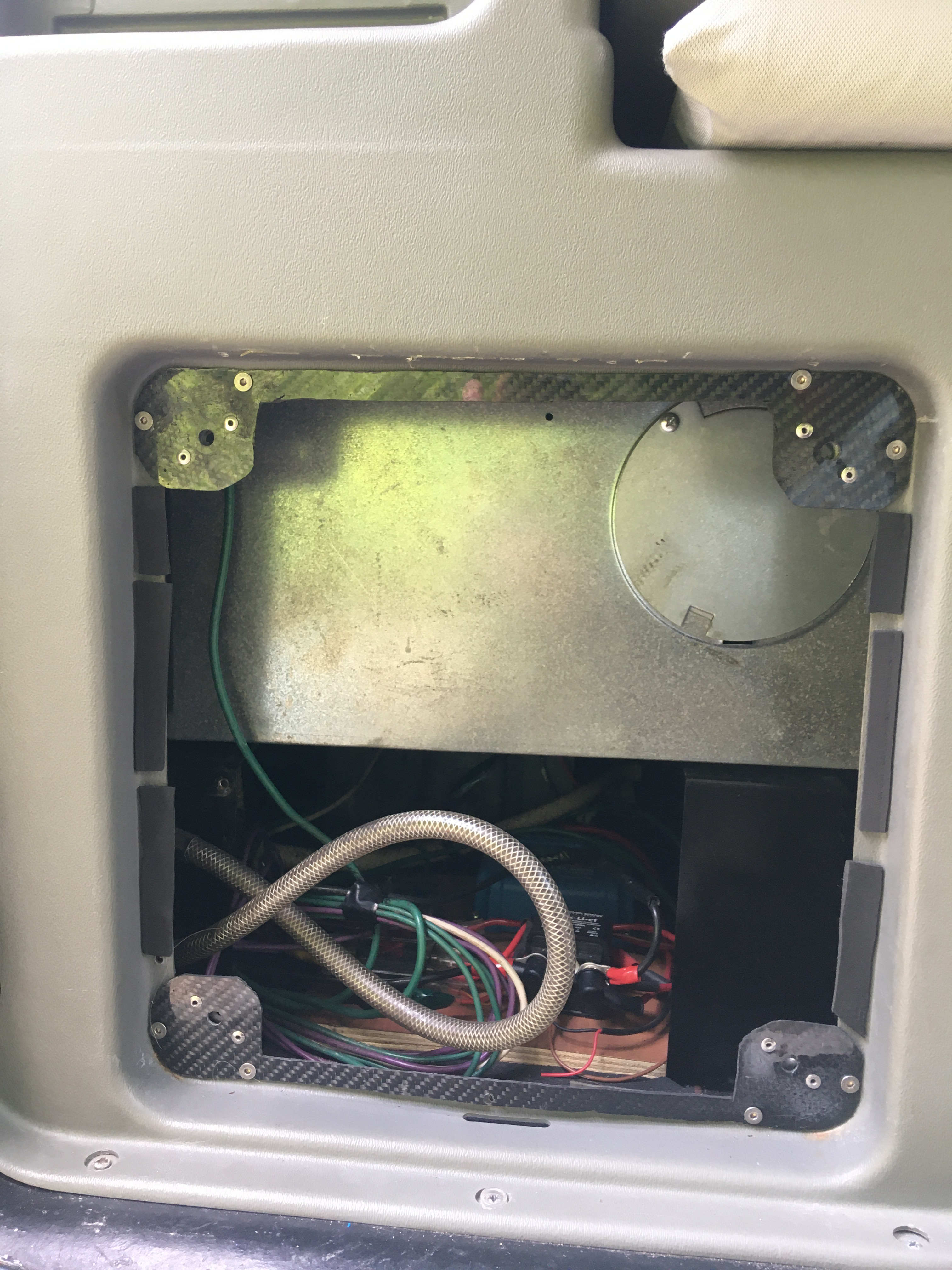
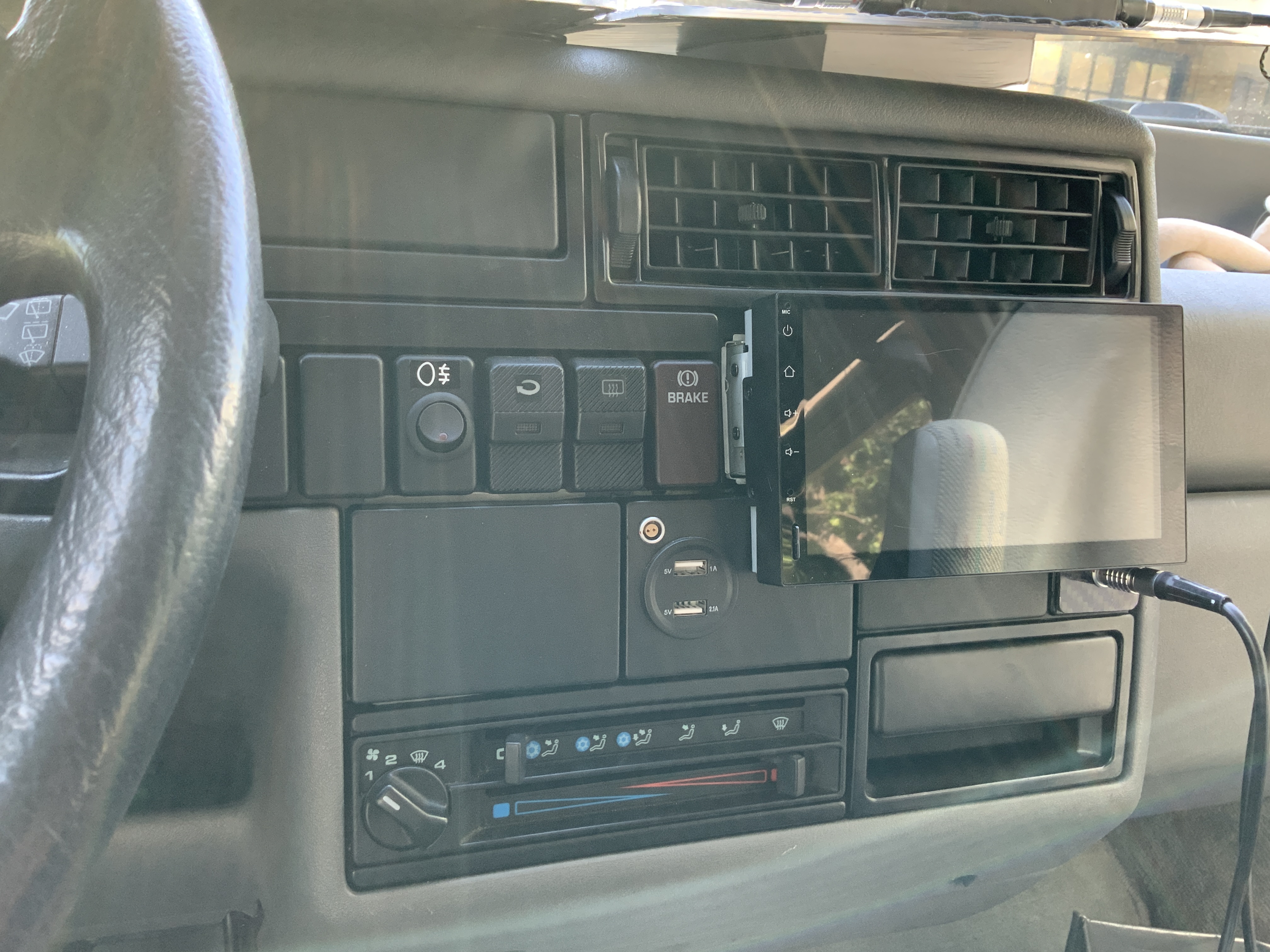
Power is terminated on a 0B Lemo chassis connector. I use a lot of these connectors in my van and for other 12V power connections. This one is 15V and the wrong gender (compared to my personal standard) so I used 0B as opposed to my usual 1B, which prevents accidents. Its a very nice compact, locking connector with excellent cable strain relief and reliability.

The LED is relocated to the side of the heatsink, held on with 3M VHB tape. The plastic holder requires a little trimming. This allows the LED to be viewed via the cooling vents.
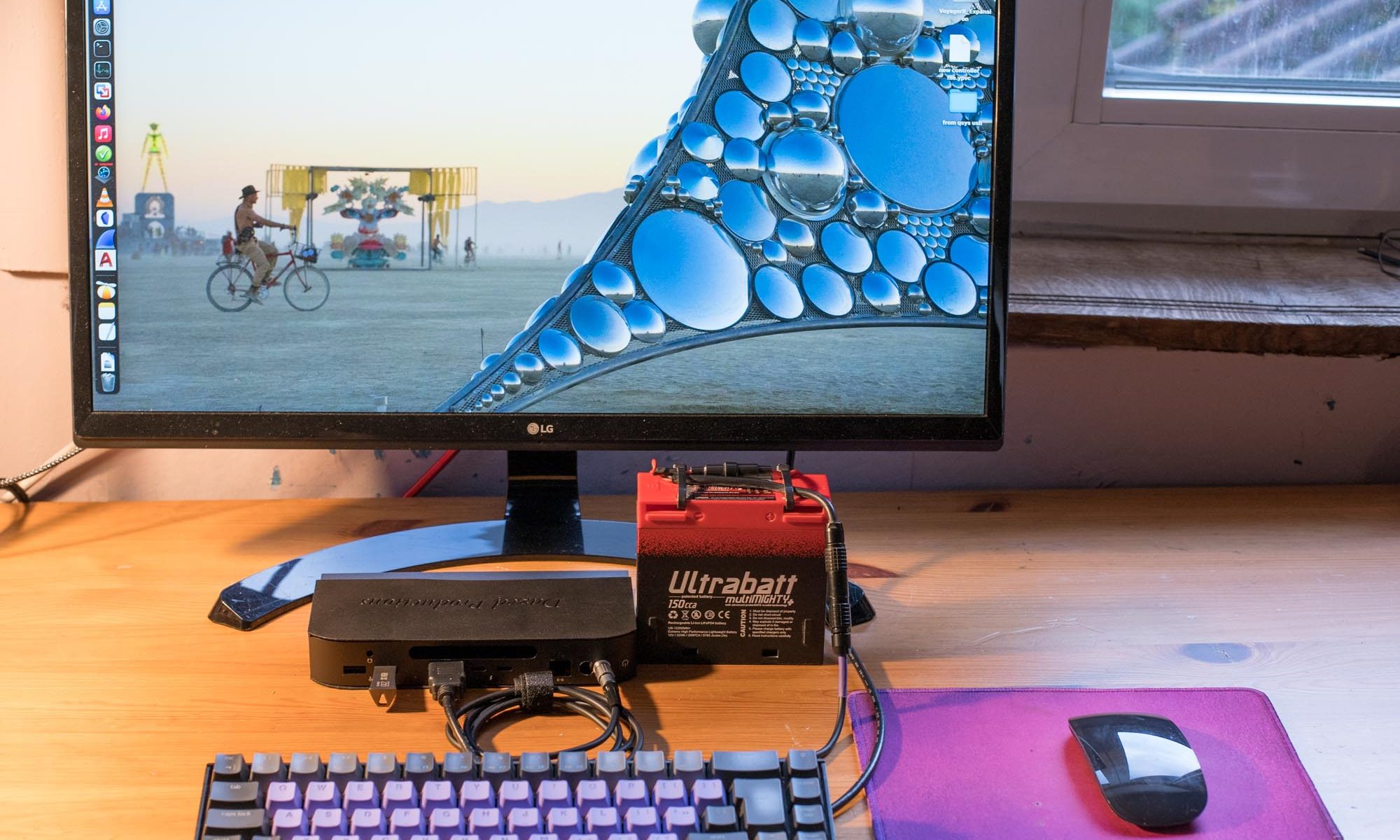
Results- Weight
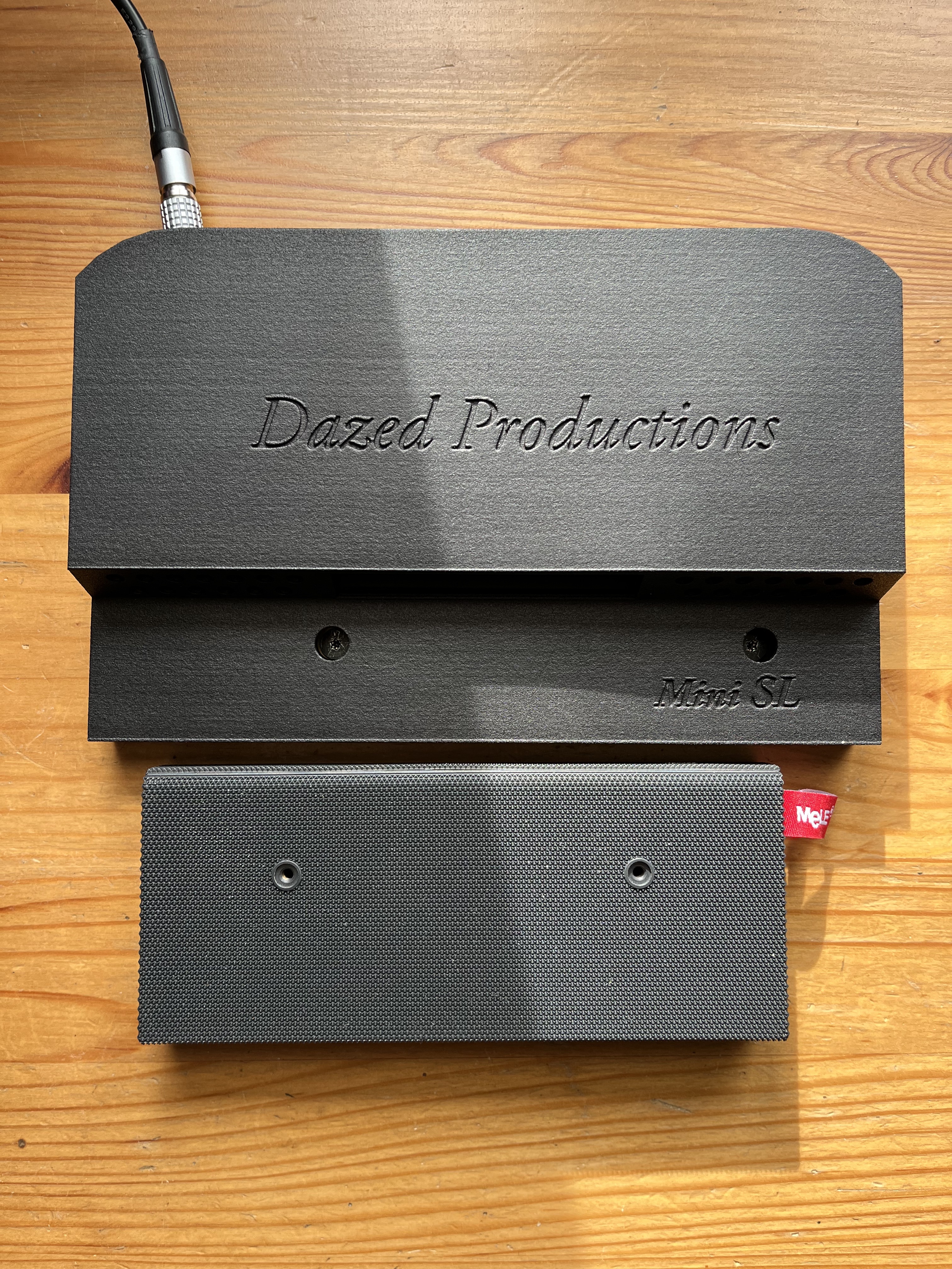
More than size, the aim of this project is light weight. Coming in under the NUC makes it a rough success. I say rough because the NUC has an M2 SSD and twin RAM slots, so it should be heavier. The Mini I suspect is a little porky due to the relatively large heatsink, I have forgotten what the Nuc one looks like but I think its probably smaller and the NUC therefore more fan dependent.Its also only a rough success in that the MiniSL is 1.8x the weight of the Mele, yes the SL has more than 1.8x the performance but CPU/GPU aside otherwise they are similar. Same 256GB Storage/8GB RAM, Both have WiFI 6 and BT5 (with mini slightly better spec), both dual 4k output, both passive cooling (although the Mele won’t overheat). The Mele also has a much more practical Micro SD card storage expansion (the SL needing a USB stick to achieve the same which is a pain when throwing in a bag). It lacks one USB-C port (and thunderbolt + Alt mode displayport)

The MiniSL now weighs less than the aluminium housing of the standard Mini!

Bare Weights
Mele PC bare weight 188g

Mac Mini M2SL bare weight- 344g

Custom 7th Gen i3 NUC bare weight- 406g

2017 Macbook 12″ no PSU- 937g

Standard Mac Mini M2 (Apple specified weight)- 1180g

Just the Mac Mini Chassis, the aluminium, no PSU, no power light, empty shell -497g

MiniSL powered with Belkin 45W adapter- 15V PD

Mains Powered Weights
Mele PC weight based on already carrying a USB-C charger for the ipad- 188g

Mac Mini M2SL with cable based on already carrying a USB-C charger for the ipad- 389g

Mac Mini M2SL with Dual output PSU and cable- 476g

2017 NUC i3 with PSU- 580g

PoE+ Powered MiniSL- 12V 2A PoE extractor

PoE Powered Weights
Mele PC with PoE+ PSU- 242g

Mac Mini M2SL with PoE+ PSU- 475g

(virtually the same as with a Mains PSU, slightly higher cable weight due to using a 2-part cable for DC powering flexibility)

Results -Power
USB-C/Mains
USB-C is really quite cool as a universal power supply and a generational jump over the 5V USB-A power. I already have lots of devices that use USB-A as a common power supply, sometimes with DC-DC conversion to get up to 12V. With USB-C one simply needs the right cable and a PSU that will output what is needed (and unfortunately some don’t). I had to upgrade the Anker PD1(which doesn’t work properly at 12V for either the Mini-SL or the Mele) to a Belkin dual output 45W adapter. This powers the Mini happily in all scenarios.

One sole issue with multiport PSUs is some drop power when re-negotiating. I have a Quad output RavPower charger, which works great but if anything new connections or disconnections are made it will drop power briefly, which will cause the MiniSL to reboot.

PoE+

PoE power was partially successful, partial fail. On PoE the MiniSL boots and will run for days. I can even max out the processor and its fine. If however, I run Geekbench it will brown out several minutes into the CPU test. It does not seem able to provide enough power for tasks which use both CPU and GPU.

Results- practicality and functionality
A combination of Apple Silicon and Ventura is just not practical for me. Even some OSX apps don’t install.Lots of playing around with windows ARM reveal that to be a real mixed bag. Its pre-release software (so no blame to be laid at Microsoft’s door). While I understand the differences (and this is a metaphor not a direct comparison) its a bit like going back to emulators rather than virtual machines. Some stuff works but its hit and miss and some vital software I just can’t run.

I have roughly the same hit rate installing a windows app with Wine as I do with windows Arm. Some installers just won’t run on ARM due to dependencies and/or the checking of dependencies. Anything requiring drivers is a no-go.
For me the end result is a powerful cool running machine with no real use case.
After creating this MiniSL, I bought the Mele PC, which while a lot slower, is a lot lighter, was a lot cheaper, will run anything I need. It also runs perfectly from PoE. It will become my main mobile compute device.
I keep my Mojave 2012 quad core i7 with its dual internal 4TB SSDs and 16GB RAM as my day to day office machine! Its flexibility trumps the speed of the M2 for me.

The Mini will become a bit of a laptop replacement for use in specific use cases and as a PoE media player. I expect it to get a fair amount of use as a desktop for the van.

For anyone that wants to replicate
This housing sleeve can easily be printed by downloading the STL and sending it to a printer. All it takes to install a Mini to the case is a M2.5 tap and a PCB with the DC presented on a connector of some sort. I did not modify the case in any other way.

A word of warning to anyone who wants to try this.  The power button has a thin ribbon cable that runs by the corner of the shield.  Its easy to catch this when manhandling it in and out of the case.  i broke mine!  Set to auto power up now (after I booted it by shorting the switch).  I recommend re-routing the cable away from the corner as it can now pass in the void where the PSU was. I managed to replace the Apple cable with a generic 0.5mm pitch 6-pin ZIF cable as the part seems completely impossible to find.

STL Link

Eurovan- LED Third Brake Light Conversion

Solving the problem you didnt realise you had!

I have curtains on the back window and you always had to manoeuvre the curtain around the 3rd brake light. Not that complicated but I was looking at swapping the curtains to the Van-X ones, which are stretch curtains. A quick measure up suggested that the 3rd brake light was going to be a real issue with the Van-X curtains.

The problem. The original rear cover mounted to the light housing blocking the curtains. LED board in the foreground.

I have been doing a bit of 3d printing recently, so after doing a bit of examining of the brake light unit, I realised that if I could put a LED board where the Hella reflector board clips in, I could make the curtains fit.

First off I found a 3rd bake light LED replacement that had an LED board the right size. Using an off the shelf module just seems so much easier as I know it meets all the right brightness requirements. I found a “GSRECY Red Lens Rear High Level Centre Stop Tail Third Brake Stop Llight Lamp For Transit MK7 2006-2013” on amazon.

Transit LED board on 3D printed back plate compared to the original Hella bulb unit.

I then designed a 3d printed backplate to mount as the Hella reflector board does and to accept the new board. It had a raised section to allow the board to mount without the cables getting in the way. I designed clips to hold the board in place (but the top ones hit the red perspex so I had to remove them and glue the board. There is a cable access hole with a cover on the back side (to make the cables exit flat against the panel) and some loops for zip ties.

Its all printed using MJF printing.

Back of the plate with the two locating areas to mount into the original clips.

The board clips in nicely and makes the 3rd brake light just the right depth for the curtains. It is attached just with butt splices, would rather have incorporated some form of connector but couldnt think of a way to make that work.

The final installation. Messed up when attaching and forgot the heatshrink so the cable could have been a bit cleaner! The original rear cover locating pins now remove.

Solar Part iii

We had a wonderfully unseasonal bit of weather at the weekend, so I took advantage and fitted the new solar panel.

250 Watts of Panasonic HIT

Its a Panasonic HIT 250w panel, which happens to be a perfect size to go on the central section of the roof. It replaces the 4 x 50w Lensun semi flex panels I had on before. The Lensuns lasted about 2.5 years after which two of them delaminated and lost their top cover. Underneath they were a sticky rubber, causing dirt and water to stick to them. I lost one out of each series string (two series strings in parallel) so the performance took a real hit.

Time took its toll on the 4x 50W Lensun panels. Having lost their top cover, water would pool on them and they lost a lot of power. Obviously the two knackered panels are in the centre.

I chose the Panasonic panel for their width and after the experience with Semi-flex panels, I wanted to try a rigid panel. It hit my power and size requirements (same or more than the lensun in terms of power and baiscally the same size). It has a useful 44v output (similar to the lensun parallel/series arrangemnent) helping to keep feed cable sizes small.

I used the Photonic universe mounting brackets/wind deflectors to mount them. I wanted a wide mounting surface and to stop wind going under the panels, both from a cabin noise and from a flight risk point of view. Using the brackets was not a simple task at all. They are designed only for 600mm panels, so I had to use two pairs cut to length (which took quite a while with a hacksaw).

I used some of the spare off cuts to make central brackets (both to hold panels but also to give them some central support). I also added some front support brackets, as side brackets get a solid

The roof is curved, and more at the front. The two bracket halves are at angles and I had to enongate the bolt holes in them to allow for some angling.

The main contacting parts of the brackets and the side brakcets are all bonded on with Plexus MA310 structural adhesive, which is recomended for use with the ASA roof . Where I still had some space to fill due to the angle of the roof , I used Sikaflex 512 to fill the remaining gaps. All the bonding areas were sanded and degreased first.

I was concerned with the extra weight (15kg panel) and compared to the lensuns, I did put the panel much lower on the roof so more of the weight moves around the pivot point. The struts seem to handle it ok. They can’t hold it at the part open state (but they couldn’t before either). It goes all the way up and stays but think there is a reduction in tension now and I can pull the roof down a lot more easliy (it needed a bit of a tug before).

Of course the rigid panels add a small amount of height compared toi the lensun panels before. I hope the neater roof will have less wind noise and be more robust though.

Winnebago table Mk.3 (freestanding)

Another long term project that I think is possibly at a conclusion. The hunt had been on for a table solution that doesn’t require taking part of the bed (I like to sleep in . . . .). It seemed a waste to have this table in the van that couldn’t be used outside of the van.

My Mk2 solution was to replace the old single leg with two off the shelf fold down table legs. These could be used either in the normal way in the van or in combination with some bolt on legs.

I am a fan of the 15mm rod system that gets used for video gear. I discovered it years ago when i used them to make a motorbike stand!

For Mk.2 I created a pair of legs using 2 x 400mm +300mm rods. I added bracing with two 200mm rods and the end caps from the 400mm rods. The legs have generic 15mm rubber stoppers/feet. To start with I used Smallrig tube clamps mounted to a carbon fibre interface plate and mounted to the table.

The end result wasn’t entirely stable, primarily due to the off the peg legs which had way too much side to side movement. I decided that there was mileage in the original idea and worked on MK3. The clamps I had used had a very small contact patch so had movement in them too, so I looked for a better clamp.

I found what looked like a more stable mount in the Smallrig dual clamp (1943), which is designed to take a dual rod but I didn’t let that small detail bother me. It seemed to offer a flat mount and 3 mounting points. When it arrived I found that one mounting point has a recess, so I found 2mm washers to space that out. Another washer to fit in the tube socket for another bolt and hacksaw the dual mount in half! Mounted to the table with bolts and structural adhesive and it seemed more stable but the other end was still wobbly so I ordered up another set of rods and another two dual mounts.

The end result, I put 3 leg mounts on one end, so I can use either a single or dual leg in the van or 4 legs out of the van. 700mm legs with 400/300mm rods joined. Sockets from 1943 clamps cut in half and fitted with stainless knurled m5 knob.

Two side bracing bars from 2 x 200mm rods and Smallrig 1104 90 degree brackets. The 1104 brackets have one of the two bolts replaced with an allen key bolt so that only the clamp for the upright is adjustable. Mounting clamps for all rods fitted to the underside of the table.

Another Eurovan new switch plate.

A lot of the eurovan blogs out there end up having a new switch plate of some sort! Times change and we need new fuctions. After getting mine, I originally modified the original by cutting in a couple of switches for the fridge and fitting 12V, USB chargning and a switch in place of the redundant 110v outlets.

My issue with this set up was primarilly that the USB and 12v cables were by the opening part of the fridge door, which always lead to cables trapped in the door. I could have re-hinged the door but the door was correct as the passenger could open it and get at drinks while we were moving. I also didn’t have a switch setup for my router (which lives under the sink)

The secondary issue is that in these coronavirus times the van is my shed office. To plug in my laptop I currently have to plug in USB-C into a modified cigarette lighter unit and plug that into my 12v outlets. It is not only a bit ungainly but I also keep running out of outlets on this side of the van (using another for wifi link and another for a NUC). I wanted to install a modified USB-C adapter

I started CADing up the plate probably 2 years ago and it got re-picked up every now and again. Everytime slightly different. I wanted to get a proffesionally made plate from the cad made out of metal but getting someone to do it was problematic. In the end I gave up. Something composite and home made is a bit more in keeping with the van anyway!

Made some carbon fibre plate and transfered all the measurements from my cad to the plate by hand. Took my time and tried to get all the holes as accurate as possible with a handheld drill and a dremel. Should really use a pillar drill but I have too many tools for my flat as it is! One of the nice things of composites is they are a lot easier to cut than metal.

Not sure what everyone else finds but my Winnebago framework is far from square. Plate had to be taller on the left to the right. My plate also has a straight line from one side to the other, which shows the bow in the metal work! Its also not flat as they never bothered to sand down the welds. . .

Left to right my plate ends up with

  • 2 x 12v direct power outlets on Lemo 1B
  • Switched Dual USB A power outlets with volt meter. Dual USB-C outlets with top delivering 30w for laptops, lower 18w for phones etc. (Its a pass through connector connected to an Anker charger modified to convert from cigarette lighter to cable input)
  • Gap for future sockets
  • Locking power switch for van 4G wifi router and associated bits
  • Fridge power
  • Livello 9-LED LPG monitor
  • Stock test switch
  • Stock levels board but with LED holes for water only
  • Water pump switch

I was tempted to get rid of the factory meters completly but seemed silly to chuck it away when i would have to recreate its functions for the water. The voltage and LPG are now hidden away as they serve no function any more.

Stereo Power

My weekend task that took a while longer than I expected! Finally got the stereo working from either the starter or the house battery. As the house battery has plenty of solar and I had upgraded all the speakers it made sense and I wish I had done it earlier.

In my case, I don’t have a split charge relay in the engine bay any more, so I have no house power there to split off. My relay is in the back. So running in cable time!

I used a Carling double pole single throw (on-on) switch to switch both the main un-switched radio feed and the aux feed that powers it up. Now in one position it works in the normal way, switched on and off with the ignition and powered from the alternator, in the second its on and all power comes from the leisure battery. I would have used some slightly larger, better fit switches but they only came illuminated and were very expensive and the Carling had more options. I got an actuator with a battery engraved on it and a purple one which was on back order but seemed more fun (and arrived the next day)

4mm cable was run in parallel with the Winnebago rear speaker cables, which meant seat out.

I ran in a 4mm thinwall cable between the switch and behind the fridge following the existing speaker cables. To lift the carpet enough the seat has to come out. This then joined onto the old fridge cable that I upgraded in the past.

In my case, my fuse box is behind the rear plate, not on it. Hated that plate!

I have a 6-way fuse board in the back which replaces the original board. I hated that thing, it was heavy, I didn’t like the loom dragging out everytime I needed to get in there, all the screw holes were stripped (wood screws into plastic is not a sensible solution) and the bloody door was always hitting me on the head.

While I was doing a bit of rewiring for the new circuit, I also took the time to modify the rear vents with metal clips for the screws and added a new set in the middle of the largest vent. All mine were stripped and the vents banged about.

End ressult, stereo with no ignition key!

Coffee shelves

Inspired by/ ideas stolen from 1705.net

Was seriously missing surfaces for the evening time, especially if the top is down. Cooker top is no use as you have to move everything when you brush your teeth. There is just the tiny area in front of the cuttlery drawer.

Wanted a small shelf that never got in the way. Although the idea started from the larger shelf on 1705s blog, I wanted something shorter. I had a failed carbon fibre project that was using 5mm Nomex honeycomb so decided to use this with some home made CF sheet to make a small, thin lightweight shelf. Some bits of bent ally with CF reinforcment completed this one. Works well for phone, keys etc.

The first coffee shelf

1705.net also had a reduced clip in shelf, using bracketry from their second unused table. My van only came with one table, so although this looked like a nice idea, I didn’t have the spare bracket to use for it. I searched high and low for an aluminium profile to match with no luck but recently came up with a way of simplifying the bracket using a hook and and a single stopper (the original having a stepped stopper section).

Bent some 3mm acylic to make the hook sections and aluminium corner to make the stopper section. Shelf constructed from 2 layers of CF and aluminium honeycomb (about 10mm thick total).

Has a bit of give in the brackets but then so does the original table bracketry! Could possibly reinforce the angle if it comes to it.

Stereo Upgrade (Pt.2)

Coronavirus upgrade time!
When I got Vanity, she had a severely damaged stereo installation. All of the cab speakers had been blown. Some made some vague noises but the paper cones in the door cards were completely broken and no longer attached. One of the tweeters worked. The only working speakers in the van were the two rear Winnebago fitted speakers. Unfortunatly, only one of the two worked as the stereo had only one channel working!

My initial upgrade path needed to give me a working stereo. Allow me to connect my tunes. Give me a reversing camera screen.

Finding a single DIN stereo that has the screen extending down (rather than up in front of the vents) proved a search. I ended up finding a cheap Android Xtrons unit.

Gives GPS via built in android app.

Gives me internet radio without a phone (I used it initially with a generic USB 4G dongle but it now works on van wifi)

Gives me my music library on a SD card which syncs to my itunes library over wifi when at home (iSyncr)

Can do bluetooth recieving.

Has reversing camera input and can have steering wheel controls

Xtrons TR704L Head unit. Dash also includes ignition switched USB charger with volt meter, Lemo 0B power for GPS and a Lemo 1B power input to battery for solar charging of starter battery (currently plugged in).


Upgrading speakers was a little tricky as the door speakers are somewhat unusual 5″ units. As a stop gap (a 2 year stop gap), I slung some 100mm full range coaxials into the existing tweeter holes (Hertz)

With some time on my hands, I went back to looking at upgrading to a tweeter/mid setup. Was considering going Hertz pro but really meant 6.5″ mids. Stumbled across Hertz’ sister company Audison selling what looks to be a cheaper variant of the Hertz legend tweeter with a 5″ mid so I got these ordered up!

Fitting of course is never quite as simple as one would hope. The holes don’t tally with the old ones and the old speakers used a plastic mounting ring inside of the door card which too small to allow the rear cage of the Audison in. First attempt I removed the door card to work out how the hell I was going to fit them. In the end, just took removing the internal plastic ring, drilling new holes and using the metal clips for the screws (which came with the speakers). for the second door, I didn’t even remove the door card and cut the internal plastic trim out with a dremel.

Arguably they just fit or dont fit depending on your point of view as they are a little deep in one corner. I padded out that corner with foam and it works.

The tweeters I decided to fit to the original tweeter speaker covers. The little pods came with the speakers and I simply drilled holes for bolts and put some foam betweent the two. Foam was also added to the grille undersides to stop them rattling. Of course nothing is simple and one of the tweaters stopped working. Not wanting to deal with the return issues, I pulled it apart and fixed a broken wire.

Finding locations for the crossovers was a challenge in itself. Ended up with one screwed into the side of the fuse box holder and one bolted under one of the airconditioning air boxes (using the screw that used to hold the thermostatic probe (which broke, is unobtainable and I replaced it with a fridge thermometer)

Connected up and as part of testing panned the audio all around the van. . . . to find that one of the rear speakers had now given up the ghost. One of the small wires that connect to the cone was faulty. Not having any Audison options in a 4×6 I put in a pair of Hertz DCX 460.3, which needed a little bit of modification to their plastic mounts to fit the original grilles but otherwise fitment was simple.

Audison Voce AV K5 system installed


Wardrobe

The original wardrobe is much hated. I hated that it had little usable storage. It had doors that were always in the way and clattered while driving.

I decided to go the shelve route and to also change the doors to a tambour door

Completed install. Dimmer for the roof LEDs and a dim/full switch is on the left beneath the one remaining cigarette socket in the van. Plate replaces what was once mains power outlets.

The shelves were mainly produced from the old cupboard doors cut up and repurposed. These were actually quite a nice, light weight hollow construction. The divider was extended at the bottom to prevent items from crossing between the two sections using some home made carbon fibre, double sided sheet. The top shelf is a sandwich construction carbon fibre shelf with aluminium honecomb core!

The brackets for the tambour doors needed spacing out to put them in line with the metal door edges. A top vanity cover is needed to hide the roller and the gap at the top. Purple carbon fibre sheet (one layer of purple glass/CF twill and rest CF). A trim is also needed for the bottom of the metal frame where screw holes were exposed from removing the old track. Access to the top shelf is slightly limited by the door.
I find aluminium corner a really simple, lightweight and flexible way of making shelf brackets.

Winnebago Gas struts in EU

I struggled to find all this info, so hopefully this will help others

Pop Top Struts

Mine was fitted with Nitrolift GS10-22-300-350. This tells you it has 10mm shaft, 300mm stroke and a 350mm body with a 22mm body diameter. It does not tell you about the rod ends or the force. The ends are 13mm ball sockets (which on nitrolift fit an M8 thread). The length of the ball sockets is 30mm from end to ball centre. In the UK SGS sell these and the socket is code B14.

Choosing a force. . .

What I found is that the stock seems to be 100lbf (444N). Heavy duty ones are sold at 110lbf (490N) and 120lbf (533N).

First off I got a standard which was dumb as I have solar on the roof. I had no idea what was fitted to my van initially and they were stronger than 444N.

I probably have about 10kg on my roof so second attempt was a 500N (112lbf). This works out much better but they still struggle to hold in the partially open state. I would go for 533N at least next time.

There are YouTube videos that show how to compress the struts with a ratchet strap and a prussic loop (loop of rope) this is really easy to do. Propping the roof is the bit that takes the longest (just finding something a good length). I used some camera rods with some books to space it all out.

Kitchen unit struts

The original struts had markings:

SPD-4900-40A

Google says this is a 40lbf (178N) strut with a 2″stroke- length between 5.5″ and 7.5″ (140-190mm). Think its 10mm ball ends, 6mm rod diameter, note that length includes ball ends.

At the time I got the van the struts had completly failed and I couldn’t find a direct replacement. I went for some a little shorter that were easily available on ebay and moved the mounting points. These were 80N small kitchen struts. They kept the lid open (apart from on a slope).

Eventually I put a magnetic knife block on the top so up-rated the struts and went back to the longer length.

I can’t find a UK 51mm stroke unit. Closest is under or over (40 , 60mm). Note that lengths of nitrolift units don’t include the ends.

Nitrolift GS6-15-60-100 rated at 160N (160mm long, 60mm stroke)

Plastic 10mm M6 ball end – 18mm length end to cetre. (complete length 196mm)

I managed to install these with the brackets back in the original hole. Took a bit of force to get them on due to the extra lenght. Work fine now, top does not raise by itself but will hold at any opening.

The knife block actually holds the knifes even over bumps etc. The block I bought wasn’t up to the job so I bought some Neodymium magnets of the same size, glued them on top of the existing cheap ferrite magnets and added spacers.